It sees the room. It never sees you.
Stillpoint is a ceiling sensor with no camera and no microphone. A 60 GHz radar counts people, tracks where they are and how they stand, flags falls, and notices someone lying completely still by the movement of their chest.
Everything is computed on the board and reported over Matter. No cloud, no account, no images, ever.
Any free heypcb account can like a board once. Likes close on November 30.
Radar on the floor side, radio on the edge
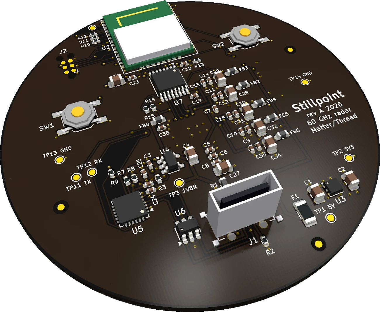
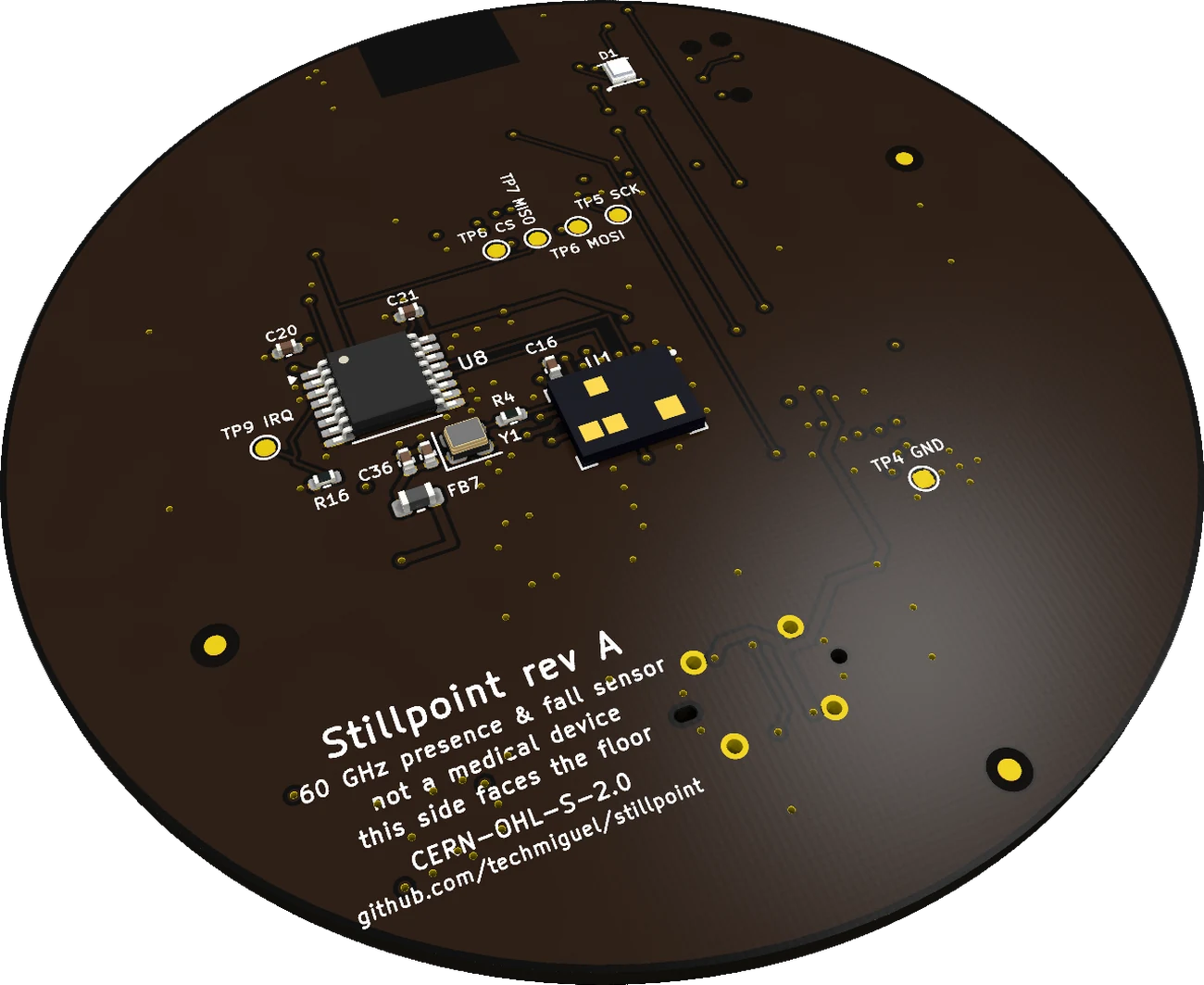
The top face faces the ceiling and carries the brains and the power. The bottom face looks at the room through a radome tuned to half a wavelength at 60.6 GHz.
 A
B
C
D
E
F
Top · faces the ceiling
- ASilicon Labs MGM260P: EFR32MG26 with Matter/Thread and its own antenna, kept clear of copper on every layer
- B3.3 V → 1.8 V translator for the radar SPI, straight below the module's pads
- CSupply filters: one lane per radar domain, 100 nF → 1 µF → 10 µF → ferrite
- DCP2102N USB console for logs at 3 Mbaud
- EVertical USB-C: power and data, the cable leaves through the lid into the ceiling
- F3.3 V LDO with its thermal pad stitched to the ground plane
 G
H
I
J
Bottom · faces the room
- GBGT60TR13C radar, antennas facing the floor; nothing but ground under it on the inner layers
- H80 MHz crystal oscillator (≤ 1 ps jitter) 4 mm from its ball
- ISecond translator for IRQ and data out, so no radar line has to cross another
- JRGB status LED, visible through the radome
Decisions taken from the datasheets
A quiet ground under the radar
Infineon asks for a solid ground right under the chip with no signal lines. Layer 2 is ground everywhere; layer 3 is the 3.3 V plane with a solid ground island cut in under the radar.
Seven supplies, seven straight lanes
Each radar domain (RF, PLL, VCO, analog, digital, loop filter, oscillator) gets its own ferrite and capacitors in one straight 0.3 mm lane, smallest capacitor closest to the ball.
Signals that never cross
The radar's control balls alternate inputs and outputs, so one translator sits on each face and the SPI moved to the module's bottom pads. Every radar line runs straight.
An antenna with room to breathe
The module sits centred on the edge with its 8.8 × 4.8 mm keep-out on all layers. A 60 mm ground plane is exactly the width Silicon Labs recommends for its built-in antenna.
Checked against the enclosure
The real board STEP goes into the FreeCAD case: 0 mm³ of interference with the shell, lid and clamp posts, and no material inside the ±60° field of view.
Every pin checked twice
ERC and DRC clean, schematic and board in sync, critical pins compared against the datasheets, BOM and pick-and-place compared against the board before ordering.
From chirp to Matter in 100 ms
The whole chain is written in portable C and tested on a PC against a Python reference, frame by frame.
- FMCW frames32 chirps of 128 samples, 3 receive channels, 10 times a second.
- Range, speed, angleRange-Doppler maps and angle of arrival from the three antennas.
- TrackingPeople become tracks; chest micro-motion reveals breathing when nobody moves.
- int8 networkA small quantised model on the MCU decides posture and falls.
- MatterOccupancy, presence per zone and a fall alert, to any Matter home.